 |
ITPS-Auto Power Sequencer and Dropout Regulator [unavailable] [http://www.cartft.com/catalog/il/337] |
|
ITPS-Auto Power Sequencer and Dropout Regulator [unavailable] [http://www.cartft.com/catalog/il/337] |
|
999.00 EUR
incl. 19% VAT, plus shipping |
| While many DC-DC
converters can operate directly from a 12 V source, it is a good idea to
regulate the car 12 V output prior to applying it to the input of the DC-DC
converter. Cars do have voltage regulation. However, in some instances the
voltage can spike up as high as 18-20 V, activating over-voltage protection
circuitry on the DC-DC converter as well as on your motherboard. Since a typical car voltage is in between 13.4-14.5 V, an LDO (low dropout) regulator can be used to provide a clean 12 V output. The ITPS was designed to work with a wide variety of ATX DC-DC converter boards as well as with other computers systems operating at 12V. The main purpose of this board is to provide power sequencing and strict 12V regulation functions for automotive systems |
||||||||||||||||||||
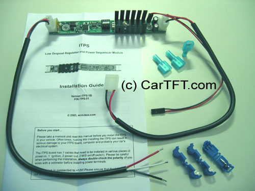
| The ITPS performs several
timing routines and takes actions as follows:
1) Ignition=OFF. Nothing happens. 2) Ignition=ON. ITPS waits for 3-4 seconds then turns on the main 12V rail. This provides enough time for battery levels to reach a stable output. After another 1 second the MCU sends an "ON" signal to the motherboard via the 2 wires connected to the motherboard's ON/OFF pins. The motherboard will turn ON and your system should start booting. 3) Ignition=ON during driving: Nothing happens. Your computer will remain ON. 4) Ignition=OFF. IPTS waits for about 5 seconds and then it turns the motherboard OFF by sending a signal to the motherboard's ON/OFF switch. Your computer should turn off gracefully (shutdown procedure). During this time, power will still be available for your PC to perform shutdown. 5) Ignition=OFF after 5 seconds. Power will still be provided for another 45 seconds, long enough for most soft shutdown processes. In the event where the shutdown process is hanging, power will be shut down hard, turning off your computer's main power source to prevent battery drain. 6) ITPS will go to step 1, until ignition is tuned ON again. |
The ITPS unit
is composed of several functions.
1) Reverse protection and resetable fuse. This function provides reverse polarity protection in case the power leads are accidentally reversed. The Polyfuse, F1 will protect against currents greater than 8A. 2) MCU. The 8 bit Microchip controller is at the heart of ITPS. The MCU controls timing and sends signals to the power switch MOSFET and controls the motherboard ON/OFF switch based on status of ignition key. 3) Power MOSFET switch circuit. Q2, the power MOSFET, controlled by the MCU, provides ON/OFF switching to the main power line. When used alone, this MOSFET can switch currents in excess of 20A. 4) LM-1084 LDO regulator. The LM-1084 is a low dropout voltage IC that provides further regulation for the ATX DC-DC converters or any other device in need of regulation. In case 12V regulation is not needed, the LM-1084 can be bypassed by applying a solder bump as described in fig 1.1. 5) PS-ON. The PS-ON circuit triggers the motherboard ON/OFF switch for 'soft' start/stop sequences. PSON is activated 5 seconds after the Ignition circuit is turned on and 10 seconds after the ignition turned OFF. |
|||||||||||||||||||
|
||||||||||||||||||||